Adding dimensions to an isometric drawing in AutoCAD LT can be surprisingly tricky, even for experienced users. Unlike standard orthographic views, isometric drawings require dimension lines and extension lines that align with the drawing’s angled axes — and the default dimensioning tools don’t automatically account for this. If you’ve ever tried applying an aligned dimension only to end up with extension lines jutting out at odd angles, you’re not alone. This guide walks through the exact workflow to get isometric dimensions right, including the critical oblique angle values that most tutorials overlook.
Why Standard Dimensions Don’t Work in Isometric Views
AutoCAD LT’s default dimension commands — DIMLINEAR, DIMALIGNED, and others — are designed for flat, orthographic drawings. When you apply them to an isometric view, the dimension lines appear correct at first glance, but the extension lines remain perpendicular to the dimension line in 2D space, not aligned with the isometric axes. This makes dimensions look misaligned and unprofessional, breaking the visual consistency of the drawing.
Isometric drawings in AutoCAD LT are technically still 2D — they simply use lines drawn at 30°, 150°, and 90° angles to simulate a 3D appearance. As a result, dimensions need to be manually skewed (obliqued) to match those same angles.
The Correct Workflow: DIMALIGNED + DIMEDIT Oblique
The solution lies in combining two commands: DIMALIGNED to place the dimension, and DIMEDIT with the Oblique option to skew the extension lines to match the isometric axes.
Here is the step-by-step process:
Step 1 — Place the aligned dimension
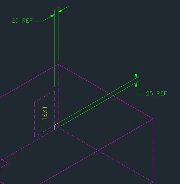
Use the DIMALIGNED command and snap to the two endpoints you want to dimension. Place the dimension line where you want it to appear. At this stage, the result will look skewed relative to the isometric surface — that’s expected.
Step 2 — Apply the oblique angle
Run DIMEDIT, then choose the Oblique option. Select the dimension you just placed, and enter the appropriate angle:
- 30° — for dimensions along the right isometric axis
- −30° (or 150°) — for dimensions along the left isometric axis
- 90° — for dimensions along the vertical isometric axis
This is where many users run into trouble. When trying to dimension vertical lines in an isometric view, the instinct is to try 0°, 30°, or −30°. However, the correct oblique angle for vertical isometric dimensions is 90° — straight up. Entering 0 or other common angles causes the extension lines to skew horizontally, which misaligns them from the vertical isometric edges.
Understanding the Oblique Angle Logic
The oblique angle in DIMEDIT controls the angle of the extension lines, not the dimension line itself. To match the isometric axes properly:
- Right-facing surfaces use extension lines at 30° from horizontal
- Left-facing surfaces use extension lines at −30° (or equivalently 150°)
- Vertical edges — those running straight up and down in the isometric view — need extension lines at exactly 90°
This is the most commonly missed detail. Users often experiment with 0°, 30°, and −30° for all three axes, and then get stuck when vertical dimensions refuse to align. The fix is simply entering 90 when prompted for the oblique angle on vertical dimensions.
How DIMALIGNED Behavior Affects Results
It’s also important to understand how DIMALIGNED determines its initial angle. The command aligns the dimension line parallel to the imaginary line connecting the two selected points. This means that if you snap to points at slightly wrong locations, the initial alignment will be off, and the subsequent oblique edit may not produce the expected result.
Always snap precisely to the endpoints or intersection points of your isometric geometry. Using object snaps (OSNAP) — specifically Endpoint and Intersection — is essential for accurate isometric dimensioning.
After applying the oblique angle, you can move the dimension line by dragging its grip to reposition it without changing the oblique setting.
Quick Reference: Oblique Angles by Isometric Axis
| Isometric Surface | DIMEDIT Oblique Angle |
|---|---|
| Right-facing (30° axis) | 30° |
| Left-facing (−30° axis) | −30° or 150° |
| Vertical (90° axis) | 90° |
Isometric Text Considerations
Dimensioning in isometric views also requires matching text orientation to the drawing. AutoCAD LT doesn’t automatically rotate dimension text to follow isometric planes. For a fully professional result, you’ll need to create isometric text styles with oblique angles applied, typically using a font set at 30° or −30° slant to match the isometric faces. This is a separate step from the dimension oblique adjustment but equally important for a clean final output.
Conclusion
Getting dimensions right in AutoCAD LT isometric views comes down to two things: using DIMALIGNED as your base command and then applying DIMEDIT > Oblique with the correct angle for each axis. The key insight that trips up most users is the vertical axis — it requires an oblique angle of 90°, not 0° or any variation of 30°. Once you internalize the three oblique values (30°, −30°, and 90°) and pair them with precise object snapping, isometric dimensioning becomes a straightforward and repeatable workflow in AutoCAD LT.
References
- Autodesk Community Forums — AutoCAD LT Forum: Is it possible to dimension in isometric view? (2019). https://forums.autodesk.com/t5/autocad-lt-forum/is-it-possible-to-dimension-in-isometric-view/td-p/8834099
- TheSourceCAD — How to Make Isometric Dimension and Text in AutoCAD. https://thesourcecad.com/how-to-make-isometric-dimension-and-text-in-autocad/