Customization is a cornerstone of professional CAD drafting, allowing engineers and architects to adhere to specific industry standards or corporate branding. In ACTCAD, one of the most efficient ways to achieve this is through the MKLTYPE command. This powerful utility enables users to transform standard drawing entities into unique linetype definitions, providing a level of flexibility that standard software packages often lack. By mastering this tool, you can create complex line patterns that include text, shapes, and symbols, ensuring your technical drawings are both precise and visually communicative.
Whether you are working on civil engineering site plans, electrical schematics, or architectural floor plans, the ability to define your own linetypes is essential. Instead of relying on the default dashed or dotted lines, you can create custom styles that represent specific utilities like gas lines, fences, or fiber optic cables. This guide will walk you through the technical process of using the MKLTYPE command to enhance your CAD workflow.
Understanding the Power of MKLTYPE
The MKLTYPE command serves as a bridge between standard drawing objects and the linetype definition engine. Unlike manual coding of .lin files, which can be tedious and prone to syntax errors, this command allows for a “What You See Is What You Get” (WYSIWYG) approach.
Key Technical Advantages:
- Versatile Entity Support: You can use lines, polylines, text, and even complex shapes as the basis for your pattern.
- Persistent Definitions: New styles are saved directly to a
.linfile, making them portable across different workstations. - Industry Compliance: Easily replicate specialized symbols required for electrical, plumbing, or landscaping projects.
- Efficiency: Once a pattern is created, it can be applied instantly to any object, saving hours of manual detailing.
Step-by-Step Guide to Creating Custom Linetypes
Creating a custom linetype involves three main phases: initializing the command, defining the pattern geometry, and selecting the reference objects.
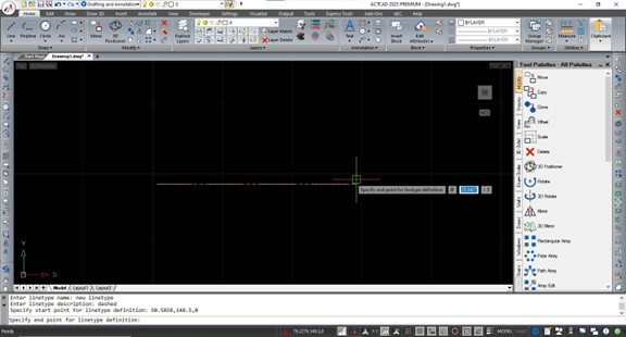
1. Initializing the Command and Saving the File
To begin, type MKLTYPE into the ACTCAD command bar and press Enter. The software will immediately prompt you to create or select a linetype file. This is a critical step because ACTCAD stores these definitions externally.
Browse to your preferred directory, enter a descriptive file name, and click Save. If you choose an existing file, ACTCAD is smart enough to append the new definition to the end of the file rather than overwriting your previous work.
2. Naming and Defining the Pattern Length
After the file is established, you must provide a name for the specific linetype (e.g., UTILITY_GAS or FENCE_LINE). Avoid using spaces in the name to ensure compatibility. You will then be asked for a brief description, which helps other users identify the line’s purpose in the Linetype Manager.
The command will then ask you to specify a start point and an end point. This distance defines the length of one repeating segment. If the distance is too short, your pattern will appear crowded; if it is too long, the symbols may be spaced too far apart.
3. Selecting Entities for the Pattern
The final technical step is choosing the objects you want to include in the linetype. You can select a combination of lines and text. For example, if you want a line that says “GAS,” you would select a short horizontal line and the text object “GAS.”
Once your selection is complete, press Enter. ACTCAD processes these entities and compiles them into a repeating pattern based on the points you defined in the previous step.
Implementing the New Linetype in Your Project
Creating the linetype is only half the battle; you must now load it into your current drawing environment to use it. This follows the standard CAD protocol for linetype management.
- Type LINETYPE or LT in the command bar to open the manager.
- Click the Load button.
- Use the File button to navigate to the
.linfile you created earlier. - Select your new linetype from the list and click OK.
Now, you can assign this linetype to layers or specific objects via the Properties palette. If the pattern appears too small or too large, remember to adjust the LTSCALE or CELTSCALE variables to reach the desired visual output.
Conclusion
The MKLTYPE command is a vital tool for any ACTCAD user looking to professionalize their technical documentation. By allowing for the seamless conversion of drawing entities into reusable linetypes, it eliminates the need for manual pattern coding and ensures consistency across complex projects. From simple dashed lines to intricate utility markers, this feature provides the granular control necessary for high-quality CAD output.
To optimize your workflow further, consider building a centralized library of .lin files that your entire team can access, ensuring that every drawing produced meets the same high standards of clarity and technical accuracy.
References
- ACTCAD Technical Documentation: Command Reference for MKLTYPE and Linetype definitions.
- CAD Standards Forum: Best practices for custom linetype naming conventions.
- Jytra Technology Solutions: Advanced drafting tutorials for ACTCAD users.