
Efficient design work often comes down to planning ahead. As drawings grow larger and more complex, you’ll likely need additional sections, elevations, and connection or foundation details. These design elements typically rely on reusable content that must display correctly at different scales depending on the drawing they appear in. Understanding AutoCAD annotative objects is one of the most reliable ways to keep that content consistent, readable, and easy to manage across every viewport in your project.
There are three common approaches for displaying annotation objects at different scales in AutoCAD: managing multiple layer representations manually, placing annotations directly in paper space at a 1:1 scale, or using annotative objects and styles that can display at multiple scales while keeping your layer structure simple. Each method has trade-offs, but annotative objects consistently offer the cleanest long-term workflow for architects, engineers, and drafters working across multiple viewport scales.
Managing Annotation Scales Manually With Layers
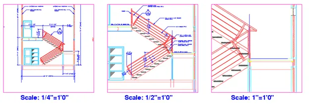
Layers have long been a popular way to control the visibility of annotation objects shown at multiple scales. For example, a layer named A-DETL-DIMS might be used for all dimensions. If you need dimensions at multiple scales, you would append the scale value to the layer name, such as A-DETL-DIMS-24 and A-DETL-DIMS-48 for 1/2″=1′-0″ and 1/4″=1′-0″ respectively.
With multiple layers defined, you then control layer visibility to display the correct dimension set based on the viewport scale. For instance, if a viewport is scaled to 1/2″=1′-0″ (1/24), you would turn on layer A-DETL-DIMS-24 and turn off layer A-DETL-DIMS-48.
In the image above, layer A-DETL-DIMS-48 is turned on in the view at the left, while A-DETL-DIMS-24 is turned on at the right; both layers are turned on in the middle view. While this method works, it requires careful naming conventions and manual layer toggling every time a scale changes — a process that becomes tedious on large, detail-heavy projects.
What Are Annotative Objects and Styles?
Annotative objects are annotations that maintain one or more representations at different scales, so you no longer need to manually adjust height, scale factor, or freeze and thaw specific layers to control final display size and visibility in a viewport. Annotative styles work much like regular annotation styles, except they manage the creation of annotative objects and control how the final height or scale of an annotation is automatically calculated.
The following object types support annotative behavior:
- Hatch patterns
- Multiline and single-line text objects and text styles
- Dimensions and dimension styles
- Geometric tolerances
- Multileaders and multileader styles
- Blocks and attribute definitions
When a model is displayed inside a viewport, the viewport scale determines which representation of an annotative object is shown. If the viewport scale doesn’t match the scale assigned to an annotative object, that object simply won’t display. In practice, this means you can assign the same text, dimension, or multileader multiple scales, and AutoCAD automatically shows only the representation that fits the current viewport — no layer juggling required.
Testing How Annotative Objects Behave
Before learning to create and modify annotative objects, it helps to see how they behave inside viewports firsthand. In this exercise, you’ll open an existing viewport in a sample drawing and change its scale, which also changes the annotation scale. As the scale changes, only the object representations matching the new scale become visible, while non-matching representations disappear.
Start by opening the file architectural_-_annotation_scaling_and_multileaders.dwg from the downloaded dataset. On the layout tabs in the lower-left corner, confirm that SECTIONS AND DETAILS is the current layout.
In the layout, locate the viewport labeled STAIR DETAIL 1 and zoom in close to it.
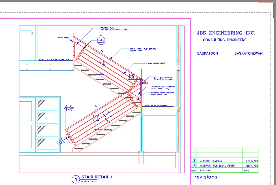
Double-click inside the viewport border to enter its model space; the border will thicken to show that model space is active. While inside, move your cursor over the text, dimensions, and multileaders — the cursor icon will resemble the head of an architect’s scale, indicating that the annotation is annotative.
On the status bar, click the Viewport Lock button to unlock the viewport, since it must be unlocked before its scale can change. With the viewport unlocked, click the Viewport Scale button on the status bar and select 1/4″=1′-0″ from the list.
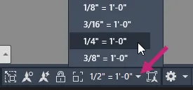
Notice that after the viewport scale changes, the view zooms out and the annotative objects update. Objects with an annotation scale of 1/4″=1′-0″ are now displayed, while those assigned 1/2″=1′-0″ become hidden. Click the Viewport Scale button again and reselect 1/2″=1′-0″ to restore the original scale and visibility. Lock the viewport again, then double-click outside its border to return to the layout and paper space.
Creating Annotative Text
Although the workflow for creating annotative text, dimensions, hatches, and other objects is similar, this section focuses specifically on annotative multiline text (MText). The main difference between annotative and non-annotative text is the style used and how the final text height is calculated, based on the display scale.
Here’s how text height is calculated for each approach:
- Non-annotative text: paper text height × scale factor = model space text height. You must calculate this manually. For example, to display text at 1/16″ (0.0625) on paper inside a viewport scaled at 1/2″=1′-0″ (factor 24), you would create text at a height of 1.5 inches (0.0625 × 24 = 1.5).
- Annotative text: you simply enter the paper text height. AutoCAD automatically calculates and displays the text at the correct model space height based on the assigned annotation scale.
To create annotative MText, open the sample file and switch to the Model tab. On the ribbon, go to View > Named Views and select Stairwell. On the Home tab, confirm the TEXT layer is current. On the status bar, click Viewport Scale and select 1/2″=1′-0″ — this scale will be assigned to any new annotative object you create.
Next, on the Annotate tab, select the ROMANS text style from the Text Styles panel, then choose Multiline Text from the text drop-down. Specify the first corner of the MText bounding box in the drawing area, type h to set the text height, enter 0.125 when prompted for the paper height, and specify the opposite corner of the box. Type STORAGE in the Text Editor, set justification to Middle Center (MC), then close the Text Editor to create the object.
Switching back to the SECTIONS AND DETAILS layout, the new MText appears in the STAIR DETAIL 1 viewport, since it was assigned a 1/2″=1′-0″ scale — but it won’t appear in the STAIR SECTION 1 viewport, which is scaled to 1/4″=1′-0″.
Adding Annotation Scales to an Annotative Object
Once an annotative object exists, you can add or remove annotation scales as needed. New scales affect how the object displays in both model space and layout viewports. To add a scale to the MText object created earlier, select it in model space, right-click, and choose Annotative Object Scale > Add/Delete Scales. In the dialog, click Add, then select 1/4″=1′-0″ from the list and click OK twice.
Returning to the SECTIONS AND DETAILS layout, the MText object now also appears in the STAIR SECTION 1 viewport, displayed at a paper text height of 1/16 inch based on that viewport’s 1/4″=1′-0″ scale.
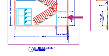 AutoCAD detail view showing the STORAGE text label now appearing correctly at the smaller 1/4 scale viewport
It’s worth noting that the AutoScale button on the status bar can automatically add the current annotation scale to every annotative object in the drawing whenever the scale changes. Use this feature carefully, since it can quickly add unnecessary scales to your annotations if left on by default.
Controlling the Visibility of Annotative Objects
Annotative objects sit on layers like any other object, but it’s best practice to place them on dedicated layers and control visibility using the current annotation scale, rather than freezing and thawing layers manually. The Annotation Visibility button on the status bar determines whether all annotative objects display regardless of assigned scale, or only those matching the current annotation scale.
To test this, switch to the Model tab, zoom to display all objects, set the Annotation Scale to 1/2″=1′-0″, and click Annotation Visibility until it turns gray (off). All non-matching annotative objects will disappear. Change the annotation scale to 1/4″=1′-0″, and only objects matching that scale will display. Turning Annotation Visibility back on (blue) restores all annotative objects regardless of scale.
Adjusting Scale Representations of Annotative Objects
When you add an annotation scale to an annotative object, a new representation of that object is created and maintained separately. You can view each representation by selecting the object. For example, a leader line assigned both 1/4″=1′-0″ and 1/2″=1′-0″ scales will show two distinct representations when the current drawing scale is set to 1/4″=1′-0″.
While all representations remain visible when an object is selected, you can only modify the representation matching the current annotation scale using grips — standard editing commands like MOVE and SCALE cannot be used to adjust individual representations. If grip editing causes representations to drift out of alignment, you can reset their positions by selecting the object, right-clicking, and choosing Annotative Object Scale > Synchronize Multiple-scale Positions.
Creating an Annotative Text Style
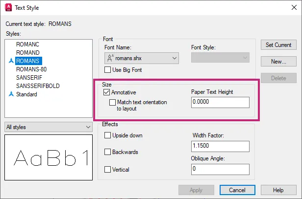
Annotative text styles aren’t required to create annotative text, but they simplify the process considerably, much like standard text styles do for non-annotative text. The key difference is the Annotative property. When this property is enabled and the style is current, any text created with it automatically becomes annotative. The Paper Text Height property defines the final text height, while Match Text Orientation to Layout determines whether text orients itself to the layout and viewport in which it’s displayed.
Converting Non-Annotative Objects to Annotative
Existing annotation and hatch objects in a drawing can be converted to annotative in just a few steps — useful when you want to make legacy content scale-aware without recreating it from scratch. Note that a block reference can only become annotative if its underlying block definition has also been updated to support it.
To convert an object, select it, right-click, and choose Properties. If multiple object types are selected, use the Object Type drop-down to pick the type you want to edit. Then, depending on the object:
- Text and MText: change the Style to an annotative style and set Text Height to the paper text height.
- Dimensions, leaders, and geometric tolerances: change the Dim Style property to an annotative style.
- Multileaders: change the Multileader Style property to an annotative style.
- Hatch objects: set the Annotative property to Yes and adjust the Scale value.
Finally, click the Annotative Scale property, use the Annotative Object Scale button to add the required scales, and repeat for any additional objects.
Setting the Annotation Scale of a Viewport
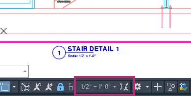
In a well-prepared sample drawing, annotation scales for each viewport on a layout typically already match each viewport’s own scale. When you create a new viewport and set its scale, the annotation scale is normally set to match automatically. If the two scales fall out of sync, click the Viewport Scale Sync button to align the annotation scale with the viewport scale — this button turns blue once the two scales match.
 AutoCAD status bar close-up showing the Viewport Scale Sync button highlighted in blue when scales match
Conclusion
If your workflow involves sections or detail views at multiple scales, annotative objects and annotation scales can dramatically simplify how you annotate a design. Instead of managing dozens of layer variants or manually recalculating text heights for every viewport, AutoCAD automatically displays the correct representation based on the scale assigned to each object and viewport. This not only saves time but also reduces the risk of inconsistent or missing annotations across sheets — a common source of costly errors in construction documentation.
Mastering AutoCAD annotative objects takes a bit of practice, but once layers, text styles, and annotation scales are set up correctly, scaling a drawing becomes almost effortless. For teams working on complex architectural or engineering projects, this feature alone can significantly streamline the documentation process.
For personalized guidance on AutoCAD workflows, annotation scaling, or broader CAD productivity questions, reach out to VietCAD for detailed consultation.
Website: www.vietcad.com
Hotline: 0913920632