Rotating views in Revit is a fundamental skill that directly impacts your project’s clarity, organization, and team coordination. When views are properly aligned and rotated to the correct orientation, your plans become easier to read, costly mistakes are significantly reduced, and collaboration with colleagues becomes far more efficient. This capability extends beyond simple aesthetic improvements—it ensures that all drawings remain consistent throughout your project documentation, making coordination with consultants and contractors substantially smoother.
Understanding how to rotate views correctly is not merely a technical skill but a workflow optimization that saves considerable time. It improves the overall efficiency of your design process and ensures that all project documents stay properly aligned with your building’s actual geometry and site coordinates. Whether you’re adjusting Plan North for better drawing clarity or rotating True North to match real-world geographic orientation, mastering these techniques will elevate your Revit proficiency and project outcomes.

What is View Orientation in Revit?
View orientation in Revit defines the direction from which you observe and display your model, determining how your building or design appears in both 2D and 3D representations. This concept is fundamental to ensuring that the right design details remain visible and properly documented. When working with floor plans, sections, elevations, or three-dimensional views, view orientation directly affects how dimensions, annotations, and design elements are presented to users and viewers.
By changing the view orientation, you gain the ability to examine your model from different angles and perspectives, which makes your project documentation significantly clearer and more precise. This is particularly important in BIM workflows where accuracy and clear communication across disciplines are paramount. Different view types in Revit provide varying levels of control over display orientation.
Floor plans present a horizontal slice of your building at a specified height, showing room layouts, walls, doors, and dimensional information with orientation based on the building’s floor level. Sections provide vertical slices through your building, revealing the internal structure and helping teams understand how floors and spaces connect spatially. Elevations offer straight-on exterior views of your building facades, displaying heights, window placements, and material specifications with fully adjustable orientation to show different building sides. Three-dimensional views provide the most flexibility, allowing you to rotate and view your model from virtually any angle using intuitive navigation tools like the View Cube or manual camera positioning for complete perspectival understanding.
A clear understanding of view orientation fundamentally enhances your working efficiency across plan, elevation, and three-dimensional views. Depending on your specific project requirements, adjusting a view’s display can substantially enhance clarity, improve coordination between disciplines, or create more compelling presentations for stakeholders. Revit provides a comprehensive range of specialized tools specifically designed for controlling and managing view orientation.
Tools for Adjusting View Orientation in Revit
Managing and adjusting views in Revit is absolutely essential to working efficiently and successfully coordinating complex projects. A properly configured view helps you thoroughly understand the design intent, detect potential issues early in the design process, and present the model with clarity and professionalism.
Whether you’re fine-tuning perspectives for specific analyses, setting up views specifically for construction documentation, examining intricate details, or creating presentation materials, controlling view orientation makes your entire workflow noticeably smoother and more accurate. The tools available in Revit for this purpose are intuitive and powerful, allowing precise control over your visual representation.
The View Cube serves as your primary navigation tool, positioned conveniently in the top-right corner of any three-dimensional view window. This interactive tool allows you to rapidly change your viewing perspective simply by clicking on its faces, edges, or corners. You can also rotate it manually to discover and settle on a specific viewing angle that best suits your analytical or presentational needs.
The Camera Tool enables you to strategically position a camera within your model to create perspective views from specific locations. This proves invaluable when you need to capture dynamic angles of your design that illustrate spatial relationships and design intent more effectively than orthographic views alone.
The View Control Bar, located at the bottom of your drawing area, provides comprehensive controls allowing you to adjust visibility settings, modify scale factors, and manage other critical view parameters. This bar makes it simple to clarify your model presentation when examining it from different orientations and helps you focus on specific design aspects.
The Rotate View Tool enables you to rotate your current view to a specific angle without making any changes to the underlying three-dimensional model itself. This proves particularly helpful when aligning views with reference lines, adjusting default orientations to match site conditions, or preparing views for sheet placement.
The Plan View Orientation is controlled through the crop region, which precisely defines the visible area of any plan view. Adjusting this crop region intelligently helps you rotate or shift the view to better accommodate complex building layouts, particularly those with irregular shapes or challenging geometric configurations.
Preparing to Rotate the View in Revit
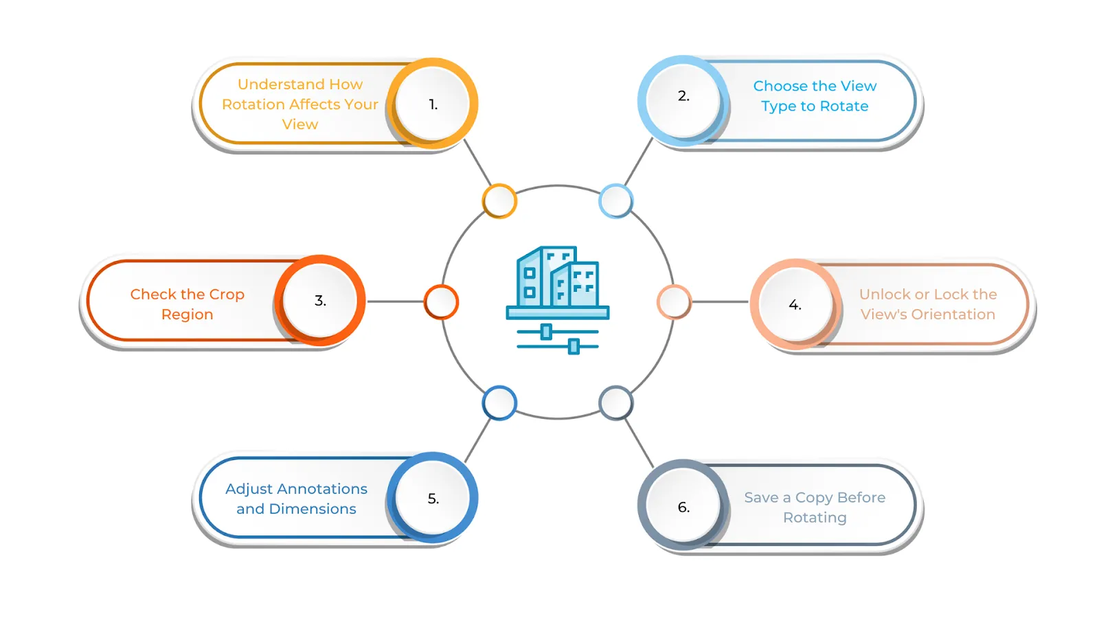
Before you begin rotating any view in Revit, ensuring that your model and workspace are set up correctly is absolutely critical. Proper preparation prevents misalignment issues that can cascade through your entire project documentation. Understanding precisely how views are positioned and how rotation affects dependent elements—such as annotations, section markers, and crop boundaries—helps you maintain consistency and accuracy throughout your project.
Thorough preparation allows for the precise adjustments necessary whether you’re rotating a floor plan for improved readability or repositioning a three-dimensional view for clearer visualization of spatial relationships. Taking these preparatory steps ensures that your workflow remains smooth, uninterrupted, and that your final design documentation stays accurate and professional.
Your first step should be to understand how rotation affects your view. It’s crucial to recognize that rotating a view changes only the way you see the model, not the model itself. However, text, dimensions, and annotations may not automatically rotate along with your view and will require manual adjustments to maintain proper alignment and readability.
Next, choose carefully which view type you need to rotate. Revit allows rotation of different view types including floor plans, three-dimensional views, sections, and elevations. When rotating a floor plan specifically, ensure the crop region aligns properly afterward, as this region directly affects the visible boundaries of your view. For three-dimensional views, leverage the View Cube or Camera tool to rotate and explore different perspectives. Sections and elevations can also be rotated, but you should carefully consider how cropping and the display of reference elements will be affected by this rotation.
Check the crop region carefully if you’re working with floor plans or sections. Ensure the crop region is visible and correctly positioned before you begin rotating. Rotating the view can sometimes misalign the crop, necessitating subsequent adjustments to ensure the correct portions of your design remain visible and properly framed.
Some views, particularly floor plans with a defined north direction, may have a locked orientation specifically to prevent accidental changes. Before rotating the view, you’ll need to unlock it to allow free movement. Once you’ve completed the necessary adjustments and verified alignment, you can lock it again to maintain consistency and prevent future unintended modifications.
Annotations and dimensions require special attention, as they do not always rotate automatically with your view. Text and labels may appear misaligned and will need careful repositioning. Similarly, dimensions aligned to a specific cardinal direction will remain fixed, meaning you may need to adjust them manually or replace them with aligned dimensions that match your new orientation.
As a best practice, always duplicate the view before making significant rotations or changes. This allows you to preserve the original orientation intact for reference purposes. Rename the duplicate view appropriately (for example, “Floor Plan – Rotated” or “Elevation – Site Angle”) so you can freely experiment with rotations without any risk of losing your original setup or reference view.
How to Rotate Views in Revit
Rotating a view in Revit helps you see, align, and present your model with greater clarity and professionalism. Using the correct methods ensures that annotations, dimensions, and other dependent elements stay properly aligned while maintaining a smooth and efficient workflow throughout your project.
The process of rotating a view in Revit is relatively straightforward, but you must take care to keep your model accurate and ensure all elements appear correctly in their new orientation. Different view types require slightly different approaches to achieve optimal results.
Rotating Floor Plans and Section Views
When you’re working with floor plans or section views in Revit, achieving the right orientation is essential for clear documentation and intuitive navigation through your project. Sometimes you may need to rotate a view to align it with an unusual building angle, improve overall readability, or meet specific project requirements or client preferences.
To rotate a floor plan or section view, begin by selecting the view you want to modify. In the Project Browser, right-click on the floor plan or section you need to rotate and select “Activate View” from the context menu. This action opens the view in your main drawing area.
Next, show the crop region if it isn’t already visible. You can do this by navigating to “Visibility/Graphics” and checking “Crop Region” under the Visibility tab. This ensures you can see and control the view’s boundaries as you make adjustments.
Now you’re ready to rotate the view itself. Open the “View” tab on the ribbon toolbar, then locate and click “Rotate View” in the “Modify” panel. Select the Rotate option from the menu that appears. Revit will prompt you to choose a base point for your rotation. Click anywhere in the drawing area to establish this rotation center point, then drag your mouse to rotate the view to your desired angle. If you need an exact angle rather than a manual rotation, you can type in a specific numerical value.
After completing the rotation, check the crop region carefully to ensure it properly frames the rotated view. If needed, select the crop boundary and adjust its handles to ensure the framing remains correct and all important design elements remain visible.
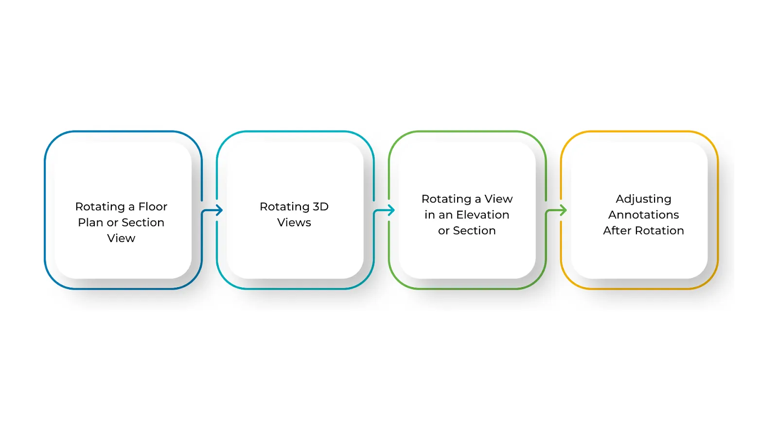
Rotating Three-Dimensional Views
Changing the angle of a three-dimensional view in Revit helps you examine design details from different perspectives, coordinate elements across disciplines, and create clear visual presentations for stakeholders. Revit’s rotation tools make navigation intuitive and provide you with precise control over your viewing angle.
To rotate three-dimensional views, start by selecting the three-dimensional view you want to work with. Open the 3D view from the Project Browser. If you’re currently in another view type, switch to the 3D view first to access its full navigation capabilities.
The View Cube is your primary tool for three-dimensional navigation. You’ll find it prominently positioned in the top-right corner of the three-dimensional view window. Click on its faces, edges, or corners to quickly rotate the view and change your perspective. This intuitive tool allows you to move between standard orientations instantly.
For more manual control over your rotation, hold down the Shift key on your keyboard and use the middle mouse button to drag and rotate the view freely. This technique gives you superior control over the angle and direction, allowing you to find the perfect viewing perspective.
If you’re using a camera positioned in your model for the three-dimensional view, you can reposition it to achieve a better viewing angle. Navigate to the View tab, click Camera, and move the camera to adjust both its location and direction. This approach is particularly useful when you want to create specific perspective views for presentation purposes.
Rotating Elevation and Section Views
In Revit, rotating an elevation or section view can help align it with sloped or angled building elements, improve overall design clarity, and make documentation substantially clearer. Rotating these views correctly ensures they stay aligned with your building’s actual geometry while keeping annotations and reference elements in their proper positions.
To rotate a view in an elevation or section, open the Project Browser and double-click on the elevation or section view you want to modify to activate it.
Unlike floor plans, elevation and section views don’t rotate as freely through standard rotation tools. Instead, you can modify their orientation using the View Properties panel, though full rotation capabilities are more limited. Access the View Properties and look for orientation settings specific to that view type.
If needed, you can slightly reposition the view within the drawing area to better accommodate your sheet layout or improve the overall design presentation. This subtle adjustment, while not a true rotation, can help optimize how your view appears on final construction documents.
Adjusting Annotations After Rotation
After rotating a view in Revit, annotations including text, dimensions, and tags may not align properly or might become difficult to read. Since these elements are typically placed based on the original view orientation, you’ll need to adjust them to maintain clear and consistent documentation.
For text and labels, you’ll need to manually move or rotate them to match your new view orientation. Select each annotation and reposition it as necessary.
Dimensions that appear misaligned after rotation should be selected and adjusted to fit your rotated view properly. You may need to relocate dimension text or reposition dimension lines to maintain clarity.
If any annotation elements look distorted or misplaced after rotation, carefully reposition them to keep everything clear, accurate, and professional in appearance.
Understanding Plan North and True North in Revit
While rotating views helps with readability and general organization, achieving precise project alignment often requires understanding and potentially adjusting both Plan North and True North. These two distinct orientation concepts are fundamental to professional BIM workflows and accurate site coordination.
 How do you Rotate a Plan North and True North in Revit?
In Revit, maintaining the correct orientation is absolutely essential for accurate design work and successful coordination across disciplines. There are two distinct types of north that require your attention: Project North, which is configured for easier drawing and intuitive layout of your model, and True North, which corresponds to the actual geographic direction and real-world site orientation.
Understanding how to rotate both of these orientation types helps ensure your design stays properly aligned with real-world geographic coordinates while remaining clear, organized, and easy for your team to work with and understand.
Rotating Plan North (View-Specific)
Plan North represents the direction used for drawing and documenting your floor plans throughout your project. It’s established to make your plans intuitive to read and maintain consistency across all your construction documents.
Plan North is adjusted strategically to present your building in a clear, logical, and organized manner specifically for construction and coordination purposes. This helps all team members work with the same reference point, making communication substantially smoother and reducing the potential for costly misunderstandings.
To rotate Plan North in Revit, open the floor plan view you want to modify and verify that the orientation is set to “Project North” in the Properties Panel. This setting ensures you’re working with the correct reference frame.
Next, enable the rotation tool by clicking on the “Manage” tab, navigating to the Position Panel, and selecting “Rotate Project North.” This opens the rotation interface specifically for Plan North adjustments.
Choose your preferred rotation method from the available options. Select “Align to View” if you want to match a specific view angle, or choose “Align to Selected Line” if you want to rotate based on a line or reference you’ve chosen in your model.
Confirm the rotation when you’re satisfied with the new orientation. Revit will update the Project North orientation while keeping True North completely unchanged. This separation ensures that your geographic reference remains accurate even as you optimize your drawing orientation for clarity.
Rotating True North (Geographic Orientation)
True North represents the real-world north, based strictly on the Earth’s geographic axis. Unlike Magnetic North, which shifts gradually over time due to Earth’s magnetic field changes, True North remains constant and reliable.
True North is absolutely essential for construction planning, architectural site coordination, solar studies, and detailed energy analysis of your building. While Plan North helps keep your drawings clear and intuitive for your design and construction teams, True North ensures your building is correctly aligned with its actual geographic surroundings and environmental context.
To rotate True North, begin by opening a site plan or selecting any view that is configured to display True North. This ensures you’re working with the correct geographic reference.
Access the rotation tool by navigating to the “Manage” tab and clicking “Position” followed by “Rotate True North.” This opens the dialog specifically for geographic orientation adjustments.
Click to select the entire model that needs to be rotated. This ensures all building elements, site features, and project geometry are rotated as a unified whole to maintain proper relationships.
Rotate to align your model with True North by entering a specific rotation angle or using reference points to align the model with the actual north direction. This ensures your building’s geographic orientation is accurate and matches real-world site conditions.
Common Challenges and Solutions in Rotating Views
Rotating views in Revit is undeniably important for adjusting your project’s orientation and improving documentation clarity, but it can present technical challenges. You might encounter issues ranging from misaligned elements and distorted views to complications with annotations and sheet layouts. Understanding these potential challenges and learning effective solutions will help you navigate the rotation process smoothly and efficiently.
| Challenge | Solution |
|---|---|
| Plan North Rotation affects all views unintentionally | In the Properties panel of the specific view, set Orientation to True North before rotating to isolate the change to that view only. |
| True North Rotation changes the entire model orientation unexpectedly | Use Rotate Project North instead if you only want to adjust plan orientation for improved readability without affecting geographic coordinates. |
| Unable to rotate the view once it’s placed on a sheet | Use Rotate on Sheet (select view > rotate) or adjust the rotation in the view itself before placing it on the construction document sheet. |
| Model appears skewed or distorted after rotation | Verify whether you need to rotate Project North or True North and adjust accordingly to correct the skew. |
| Linked models do not rotate correctly with your project | In the Manage Links settings, adjust the rotation parameters or use the Shared Coordinates tool to ensure proper alignment between linked files. |
| Annotations and text remain fixed after view rotation | Select annotations individually and manually adjust their orientation, or use a rotated view specifically for better alignment of these elements. |
| Cannot select the proper rotation axis for your needs | Use the Align Selected Line or Plane option when rotating Project North to achieve precise control over the rotation axis. |
| Rotation causes misalignment with the Site Plan | Use the Acquire Coordinates tool to match the site’s True North before rotating the project to prevent coordinate misalignment. |
Professional BIM practices contribute to sustainable design outcomes and environmental responsibility in our industry.

Conclusion
Mastering the techniques for rotating Plan North and True North in Revit directly contributes to keeping your drawings clear, organized, and your projects properly aligned with both design intent and real-world geographic conditions. Using Plan North strategically improves your documentation readability while ensuring your team works from consistent reference points. Simultaneously, True North ensures accurate site coordination and enables precise analyses such as solar studies and energy modeling.
Regular practice with these rotation techniques will make the entire process increasingly intuitive and efficient, allowing you to work faster while avoiding costly errors in coordination and documentation. The more you experiment with different project scenarios and building configurations, the more confident and proficient you’ll become, making it significantly simpler to handle even the most geometrically complex projects with smooth, professional workflows.
Developing mastery in view rotation and orientation management represents an investment in your professional BIM capabilities that will benefit every project you undertake throughout your career. Your improved competency in these fundamental skills will be evident in the quality, clarity, and professionalism of your project documentation and your team’s overall coordination effectiveness.