This guide delves into the practicalities of incorporating text into AutoCAD linetypes, building upon foundational knowledge of linetype creation. Whether you’re a seasoned CAD professional or looking to enhance your drawing standards, understanding how to embed text within linetypes can significantly improve clarity and efficiency in your technical drawings. We’ll explore the nuances of text styles, the definition process, and specific considerations for imperial units.
The ability to create custom linetypes is a powerful feature in AutoCAD, allowing users to represent various line types beyond the standard offerings. When this capability extends to including text, the applications become even more diverse, useful for marking specific components, indicating material types, or denoting special conditions directly within the line itself. This article aims to demystify the process, offering actionable insights and solutions to common challenges encountered when defining text-based linetypes.
Mastering Text Styles for Linetypes
While AutoCAD offers flexibility in choosing text styles, creating a dedicated style for linetypes is highly recommended for consistency and control. A common practice is to name this style something concise and cryptic, such as “LINETYPES.” Crucially, this text style should be defined with a Height of ‘0’. This setting ensures that the text’s size is controlled by the linetype scaling, rather than an absolute height.
It’s important to note that while linetype definitions will respect text style settings like Font Name and Font Style, they will disregard “Effects” such as Oblique Angle. If your drafting standards rely on obliqued text for differentiation (e.g., existing vs. proposed lines), you will need to adapt your text standards or explore alternative methods for indicating such distinctions within your linetypes. This limitation is a key reason why many users favor True Type fonts within AutoCAD. For instance, using a True Type font like Arial allows for the creation of an italic font style, offering a way to visually distinguish text without relying on the unsupported oblique effect.
Defining Your Text-Based Linetype
Once your dedicated text style (e.g., “LINETYPES”) is established, the next step is to draw the linetype at a 1:1 scale. This means if you intend for the text within your linetype to be 0.1 inches tall in the final drawing, you should draw the text at that size. Subsequently, use the Make Linetype (MKLTYPE) command. Follow the command prompts carefully to define your new linetype, ensuring that the text elements are correctly incorporated into the pattern.
Ensuring Upright Text in Linetypes
For users of AutoCAD 2011 and later versions, the Make Linetype (MKLTYPE) command automatically incorporates the “Upright” linetype property. This feature ensures that the text within your linetypes remains plan readable, meaning it won’t appear upside down regardless of the viewing angle or orientation. Linetypes created in versions prior to AutoCAD 2011 may need manual updating to benefit from this property.
To update older linetype definitions, open the corresponding .lin file in a text editor like Notepad. Within the linetype definition, locate and replace any “R=0.0” parameter (if present) with “U=0.0”. This simple modification enables the upright text functionality.
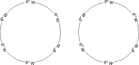
Handling Inch Marks in Linetypes
When working with imperial units, displaying the inch mark (quotation mark) within linetypes can be a common requirement. A typical linetype definition might include text like “[6″ W]”. However, AutoCAD often interprets the quotation mark as the end of the text string, ignoring subsequent characters. A practical workaround for this issue is to use two single quotes (”) within your text string where a quotation mark is needed. When rendered in AutoCAD, this combination closely resembles a single inch mark, effectively preserving the intended text.
By implementing these techniques, you can successfully create linetypes that incorporate text clearly and accurately, enhancing the informational content of your drawings. The final result should be a linetype that visually represents your intended annotation, as demonstrated in the illustration below.
These methods provide a robust framework for creating text-based linetypes in AutoCAD, significantly boosting drawing clarity and adherence to standards.