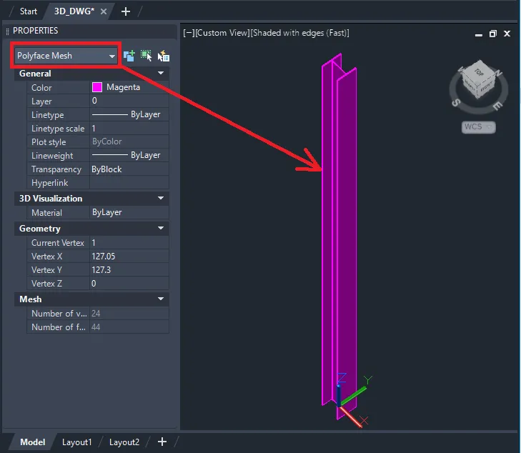
When working with Tekla Structures and AutoCAD in tandem, one of the most common frustrations engineers and BIM coordinators encounter is the polyface mesh problem. You export a 3D DWG from Tekla Structures, open it in AutoCAD, and instead of clean, editable 3D solid geometry, you get a collection of polyface mesh objects that are difficult to work with downstream. This guide walks you through exactly why this happens and how to convert those polyface meshes into proper 3D solids using a reliable AutoCAD workaround.
Why Tekla Structures Exports Polyface Meshes Instead of Solids
By default, the 3D DWG export in Tekla Structures relies on the Open Design Alliance (ODA) toolkit to generate the DWG format. This toolkit represents 3D geometry as polyface mesh objects rather than native CAD solids. Within the Export 3D DWG dialog box in Tekla Structures, there is no built-in option to convert model objects directly into solid geometry during the export process itself.
This is not a bug — it is an architectural limitation of how the ODA toolkit handles geometry translation. The practical consequence is that structural members, plates, and other Tekla model elements land in AutoCAD as tessellated mesh surfaces rather than boundary representation (B-Rep) solids.
The workaround requires post-processing inside AutoCAD itself, following a three-stage conversion pipeline: PolyfaceMesh → Mesh → Convert to Solid.
Prerequisites
Before starting, make sure you have:
- A 3D DWG file exported from Tekla Structures (any supported version from 2020 through 2026)
- A recent version of AutoCAD with the 3D Modeling workspace and the Mesh ribbon tab available
- Familiarity with basic AutoCAD commands and the ribbon interface
Step-by-Step Conversion: Polyface Mesh to 3D Solid
Step 1 — Open the Exported DWG in AutoCAD
Launch AutoCAD and open the DWG file you exported from Tekla Structures. Once the file is loaded, switch to the 3D Modeling workspace. You can do this from the workspace switcher in the status bar at the bottom of the screen or via the View menu.
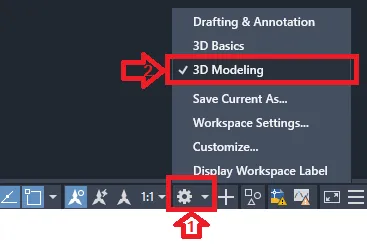
Working in the 3D Modeling workspace ensures that the Mesh tab and all mesh-related tools are accessible on the ribbon, which are not visible in the default 2D Drafting & Annotation workspace.
Step 2 — Access Mesh Tessellation Options
On the ribbon, click the Mesh tab. Inside the Mesh panel, locate the small down-facing arrow — clicking it expands the panel and opens the Mesh Tessellation Options dialog. This is where you configure how AutoCAD interprets and subdivides the mesh geometry before conversion.
Step 3 — Select Objects and Configure Tessellation Settings
Within the Mesh Tessellation Options dialog, click Select objects to tessellate, then pick the mesh objects in your model and press Enter to confirm the selection.
For the tessellation configuration, the recommended settings are:
- Mesh type: Mostly Quads
- Click the Mesh Primitives button, then select Box
- Set Tessellation Divisions to Length 3, Width 3, Height 3
These values strike a balance between geometric accuracy and file manageability. Setting divisions too high can inflate file size significantly, while values that are too low may introduce visible faceting in curved members. Click OK to confirm, then OK again to close the dialog.
Step 4 — Set the SMOOTHMESHCONVERT Variable
At the AutoCAD command prompt, type SMOOTHMESHCONVERT and press Enter. You will be prompted to enter a value. The two practical options are:
- Value 3 — Converts mesh to a solid and merges coplanar faces, producing cleaner geometry with fewer unnecessary faces. Recommended for most structural export workflows.
- Value 2 — Converts mesh to a solid but retains all tessellation faces without merging. Useful when you need to preserve the full mesh topology for analysis or downstream processing.
Choose the value that best matches your project requirements.
Step 5 — Execute the Convert to Solid Command
With the SMOOTHMESHCONVERT value set, navigate to the Mesh tab on the ribbon and locate the Convert Mesh panel. Click Convert to Solid, select the objects you want to convert, and press Enter.

AutoCAD will process the selected mesh objects and output native 3D solid geometry. Depending on the complexity and number of objects, this operation may take a few seconds to complete.
End Result
After the conversion, your Tekla Structures model elements will exist in AutoCAD as proper 3D solid objects — fully selectable, measurable, and compatible with AutoCAD solid editing tools such as SOLIDEDIT, UNION, SUBTRACT, and INTERFERE.
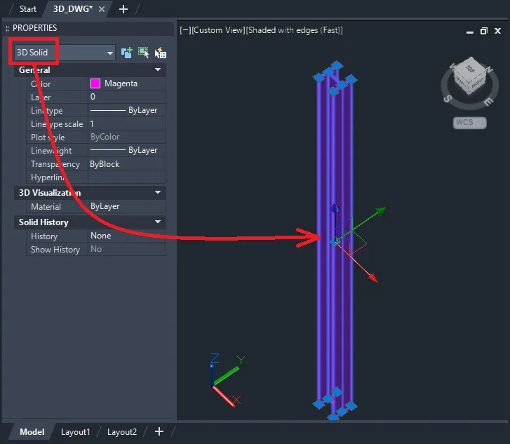 Converted 3D solid geometry in AutoCAD after polyface mesh to solid conversion
This makes the geometry significantly more useful for interference checking, section cutting, quantity takeoffs, and coordination workflows that rely on solid model data rather than surface meshes.
Key Takeaways and Practical Recommendations
The core limitation here — the ODA toolkit defaulting to polyface mesh output — is unlikely to change in the near term, which means this AutoCAD post-processing workflow will remain relevant for most BIM and structural coordination teams using Tekla Structures alongside AutoCAD-based tools.
A few practical notes to keep in mind:
- This workflow applies to all Tekla Structures versions from 2020 through 2026, as the export behavior is consistent across these releases
- The Mostly Quads tessellation setting tends to produce the most conversion-friendly mesh topology; avoid Triangles Only if solid output is your goal
- If your model contains highly complex curved geometry (e.g., curved beams, irregular haunch plates), review the converted solids visually to confirm geometric accuracy before sharing downstream
- For large models, consider converting objects in batches rather than all at once to avoid performance issues or command timeouts
For additional compatibility information, the Supported AutoCAD Versions in DWG Export article on the Tekla support portal lists which AutoCAD releases are validated against the Tekla DWG export pipeline.
References
- Tekla Structures Support Portal — Exporting 3D DWG/DXF
- Tekla Structures Support Portal — Supported AutoCAD Versions in DWG Export
- Autodesk AutoCAD Documentation — SMOOTHMESHCONVERT system variable
- Open Design Alliance (ODA) — DWG/DXF Toolkit technical documentation