Introduction
Sheet metal design is a cornerstone of modern manufacturing, enabling the creation of complex, precise, and durable components from flat metal sheets. In Autodesk Inventor, designing sheet metal parts is streamlined with specialized tools that allow engineers to model folded and flat patterns seamlessly. Whether you’re creating a simple bracket or a complex enclosure, understanding the nuances of sheet metal parts, such as bend radius, relief size, and flat pattern generation, is essential for efficient and accurate production.
This guide explores the fundamentals of sheet metal design in Autodesk Inventor, from creating parts using templates to advanced techniques like contour flanges, corner chamfers, and unfolding/refolding. By the end, you’ll have a clear understanding of how to leverage Inventor’s capabilities to optimize your sheet metal workflows.
Understanding Sheet Metal Parts in Autodesk Inventor
Core Concepts
A sheet metal part in Autodesk Inventor begins as a flat metal sheet with a defined thickness. During the design process, parameters like bend radius and relief size are consistently applied across the part. For example, when you create a flange, the bend radius is automatically added, ensuring uniformity and manufacturability.
One of the most critical steps in sheet metal design is converting a folded model into a flat pattern. This transformation is necessary for manufacturing, as it provides a 2D representation of the 3D part. You can toggle between the folded and flat pattern views by double-clicking the Folded Model or Flat Pattern browser nodes.
Key Notes:
- Mass and volume are most accurately calculated from the flat pattern.
- Moment of inertia must be computed from the final folded shape.
- Features added to the flat pattern using commands on the Flat Pattern tab are not visible when viewing the model in its folded state.
Creating Sheet Metal Parts: Methods and Workflows
Autodesk Inventor offers multiple ways to create sheet metal parts, each suited to different design requirements:
1. Using a Sheet Metal Template
- Start with a sheet metal template that includes predefined settings for material thickness, bend radius, and corner relief.
- Use sketch commands to create the base face or initial flange profile.
- Exit the sketch and add sheet metal features, such as flanges, bends, or punches, to complete the part.
2. Converting a Standard Part to Sheet Metal
- Design a standard part with uniform thickness.
- Convert it to a sheet metal part, which activates the Sheet Metal tab and adds sheet metal-specific parameters.
- Note: Converting a sheet metal part back to a standard part removes the flat pattern and restores standard modeling commands.
3. Building from Surfaces
- For parts with specific conditions, create a series of surfaces, stitch them together, and then thicken them to form a sheet metal part.
4. Top-Down Design for Multi-Body Parts
- Use top-down design to create multiple sheet metal parts in a single Part file.
- The Create Flat Pattern command is unavailable for multi-body parts. Instead, use Make Components or Make Part to create derived parts that can be flattened.
Advanced Sheet Metal Features
Flanges and Bends
Flanges are essential for adding strength and functionality to sheet metal parts. In Autodesk Inventor, you can create various types of flanges, including:
- Contour Flanges: Created from an unconsumed or shared open profile sketch.
- Lofted Flanges: Use sketch geometry to define the inner, outer, or material plane of the flange.

- Hems: Added to provide extra material thickness along an edge.
- Folds: Straight bend lines that terminate at the edges of a face.
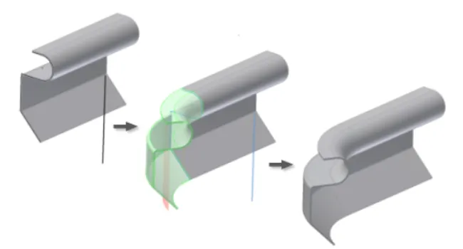
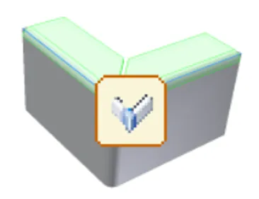
Corners and Edge Treatments
Sheet metal parts often require specialized corner treatments to ensure manufacturability and safety:
- Corner Chamfers: Applied to remove sharp edges from flat faces.
- Corner Rounds: Added to both inner and outer corners, with options for different fillet sizes in a single operation.
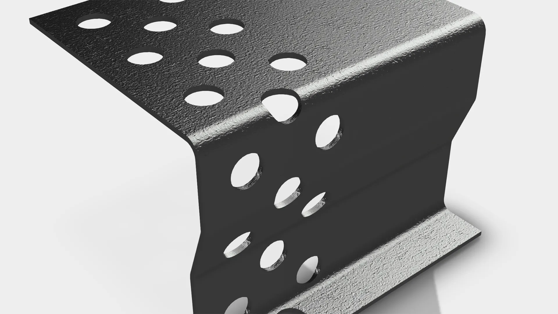
Punches and Cutouts
- Punch Tools: Use iFeatures to create simple or complex hole shapes, including those on bends.
- Rips: Required for closed profile sketches to enable flattening, especially in transition shapes like lofted flanges.
 Punch tool applied to a sheet metal face
Patterns and Repetition
- Patterns of Sheet Metal Features: Special considerations apply when creating patterns to ensure they unfold correctly.
- Bend Tables: Define bend limits for specific material thicknesses, radii, and angles to assist the flat pattern analyzer.
Working with Flat Patterns
Generating and Editing Flat Patterns
- A flat pattern represents the shape of the sheet metal part before it is formed, making it essential for manufacturing drawings.
- You can create a flat pattern from a sheet metal model and display accurate iProperties for both folded and flat states.
- Bend Order Annotation: Reorder or override the bend sequence directly on the flat pattern.
Exporting Flat Patterns
- Export flat patterns to industry-standard formats for CNC production.
- Use cosmetic centerlines to represent folded model features on flat patterns and subsequent drawings.
Custom Unfold Equations
- Use custom equations to precisely control how bend regions are flattened in your sheet metal part models.
Best Practices for Sheet Metal Design
- Consistency in Parameters: Ensure bend radius, relief size, and material thickness are consistent across the part to avoid manufacturing issues.
- Flat Pattern Accuracy: Always verify the flat pattern for accuracy, as it directly impacts production.
- Use Templates: Leverage sheet metal templates to streamline the design process and maintain consistency.
- Top-Down Design: For complex assemblies, use top-down design to manage multiple sheet metal parts efficiently.
- Avoid Multi-Body Parts: The Create Flat Pattern command is not available for multi-body parts. Use Make Components or Make Part instead.
Adding Fasteners and Assembly Considerations
When working with sheet metal parts in assemblies, sheet metal fasteners are available through:
- Bolted Connection Component Generator
- Content Center
These tools simplify the process of adding fasteners, ensuring proper fit and alignment in your assemblies.
Why Use Genuine Autodesk Software?
While cracked versions of Autodesk software are widely available online, they come with significant risks:
- Security Vulnerabilities: Cracked software often contains malware or spyware.
- Lack of Support: No access to official updates, bug fixes, or customer support.
- Legal Risks: Using unlicensed software can result in legal consequences for individuals and businesses.
Tân Đức, a Gold Partner of Autodesk in Vietnam, specializes in distributing genuine Autodesk software, including PDMC Collection, Autodesk Inventor, and Autodesk Vault Pro. Our team of engineers provides 24/7 support, ensuring you select the right product package at an optimal cost. Contact us for a free trial, direct pricing, or information about training sessions and workshops tailored to the needs of Vietnamese businesses.