AutoCAD users—especially beginners transitioning from metric units—often struggle when working with architectural measurements. The keyword “[keyword]” is commonly associated with setting up and using feet and inches correctly inside AutoCAD, particularly when drafting floor plans, architectural layouts, or construction drawings. Understanding how AutoCAD interprets units is essential to avoid scaling errors and miscommunication in design projects.
This guide breaks down how to configure AutoCAD for feet and inches, how to input measurements correctly, and how to fix common issues users face when switching from millimeters to imperial units.
Understanding Units in AutoCAD for [keyword]
Before drawing anything in feet and inches, it’s important to understand how AutoCAD handles units. Unlike some design software that locks you into a specific measurement system, AutoCAD is unitless by default. This means:
- A value like “1” can represent 1 inch, 1 mm, or 1 foot depending on setup
- The interpretation depends on drawing units configuration
- Precision settings affect how values are displayed, not how they are stored
For users searching “[keyword]”, the key issue is usually not drawing itself, but incorrect unit configuration.
Setting Up Architectural Units (Feet & Inches)
The most common and recommended method for working in imperial measurements is setting Architectural units.
Steps to configure units:
Type
UNITSin the command lineSet Length Type to:
- Architectural
Set precision as needed (0, 0.00, etc.)
Confirm and exit
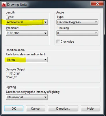
Once set, AutoCAD will interpret inputs like:
2"→ 2 inches2'→ 2 feet2'3-1/2"→ 2 feet 3.5 inches6→ 6 inches (default behavior in architectural mode)
This is the foundation for correctly working with [keyword]-related workflows.
Configuring Drawing Templates for Imperial Use
Starting from the correct template can save significant time and confusion.
Recommended setup:
Use
acad.dwt(imperial template)Or select No Template – Imperial
Verify system using:
DWGUNITS
This ensures your environment is already aligned with feet and inches before you begin drafting.
Inputting Feet and Inches Correctly
A major confusion point for new users is how to enter dimensions during drawing commands.
Example: Drawing a rectangle 12’ x 15’
Type
REC(Rectangle command)Pick first point anywhere
Enter:
@12',15'
This tells AutoCAD:
- Move 12 feet in X direction
- Move 15 feet in Y direction
The result is a properly scaled rectangular shape.
For line input:
@10'
@5'6"
@2'-3"
These formats are essential when working with [keyword]-based drafting workflows.
Adjusting LUNITS and DIMLUNIT for Display Control
Beyond drawing input, users often want to control how measurements appear.
Two important system variables:
1. LUNITS (Linear Units)
Controls how AutoCAD interprets coordinate input format.
2. DIMLUNIT (Dimension Units)
Controls how dimensions are displayed.
Recommended settings for architectural work:
- Set both to Architectural format
- Ensure dimensions show feet and inches instead of decimal values
You can set them directly in the command line:
LUNITS → 4
DIMLUNIT → 4
Common Problems When Using Feet and Inches in AutoCAD
Many issues reported under “[keyword]” discussions come from misunderstanding unit scaling.
1. Everything is measured in inches instead of feet
This happens because:
- Architectural mode treats 1 unit = 1 inch
2. Grid does not match expected dimensions
Cause:
- Grid spacing is set in inches, not feet
3. Rectangle or line sizes appear incorrect
Cause:
- Missing feet symbol (
') in input
4. Confusion between coordinates and real-world size
AutoCAD uses:
- X, Y coordinates for placement
- Not “object size” feedback by default during drafting
Fixing Grid and Snap for Accurate Drawing
To better visualize real-world scale:
- Set GRID spacing to 1′ (12 inches)
- Set SNAP spacing to 1/2′ or 1′
- Ensure both X and Y spacing are consistent
This helps align visual reference with actual architectural measurements when using [keyword]-based setups.
Practical Example: Drawing a 12’ x 15’ Room
Let’s combine everything into a real workflow:
Set units to Architectural
Start a new drawing using Imperial template
Type:
RECSelect first corner point
Enter:
@12',15'
Result:
- A correctly scaled 12×15 feet room layout
- Ready for walls, doors, and furniture placement
Internal Workflow Tips for Efficiency
To improve productivity when working with [keyword]:
- Always start from an imperial template
- Save a custom template with preset units
- Use object snaps (OSNAP) for precision
- Turn on dynamic input to preview dimensions
- Standardize dimension styles early in the project
Conclusion
Working with feet and inches in AutoCAD is not difficult once the system is properly configured. The key to mastering “[keyword]” lies in:
- Setting Architectural units correctly
- Using proper input syntax (
'and") - Understanding how AutoCAD interprets unitless values
- Configuring dimension and display settings for clarity
Once these foundations are in place, drafting architectural layouts such as rooms, buildings, and site plans becomes significantly more efficient and accurate.
For best results, always begin your project with the correct template and unit setup, ensuring consistency across all drawings.
References
- Autodesk AutoCAD Official Documentation
- Autodesk Community Forums (Architecture & Engineering discussions)
- AutoCAD User Guide – Units and Measurement Settings
- Industry drafting standards for architectural drawing conventions