Managing AutoCAD linetypes and efficiently isolating objects are fundamental skills that separate novice drafters from seasoned professionals. Whether you are working on complex mechanical assemblies or detailed architectural plans, understanding how to control linetype scaling and leverage the isolate tool can dramatically improve your workflow accuracy and drawing readability. This guide provides a deep dive into these essential features, ensuring your drawings are not only technically precise but also visually consistent across different scales and layouts.
Controlling Linetypes by Layer and Object
Linetypes are the visual language of technical drawings, conveying whether a line represents a hidden edge, a centerline, or a boundary. In AutoCAD, control over these linetypes is exercised either at the layer level for global consistency or at the individual object level for specific exceptions.
Setting Linetypes for Layers
Managing linetypes by layer is the most efficient method for maintaining drawing standards. To adjust the linetype of a specific layer, navigate to the Home tab on the Ribbon and locate the Layers panel. Click the Layer Properties button to open the Layer Properties Manager.
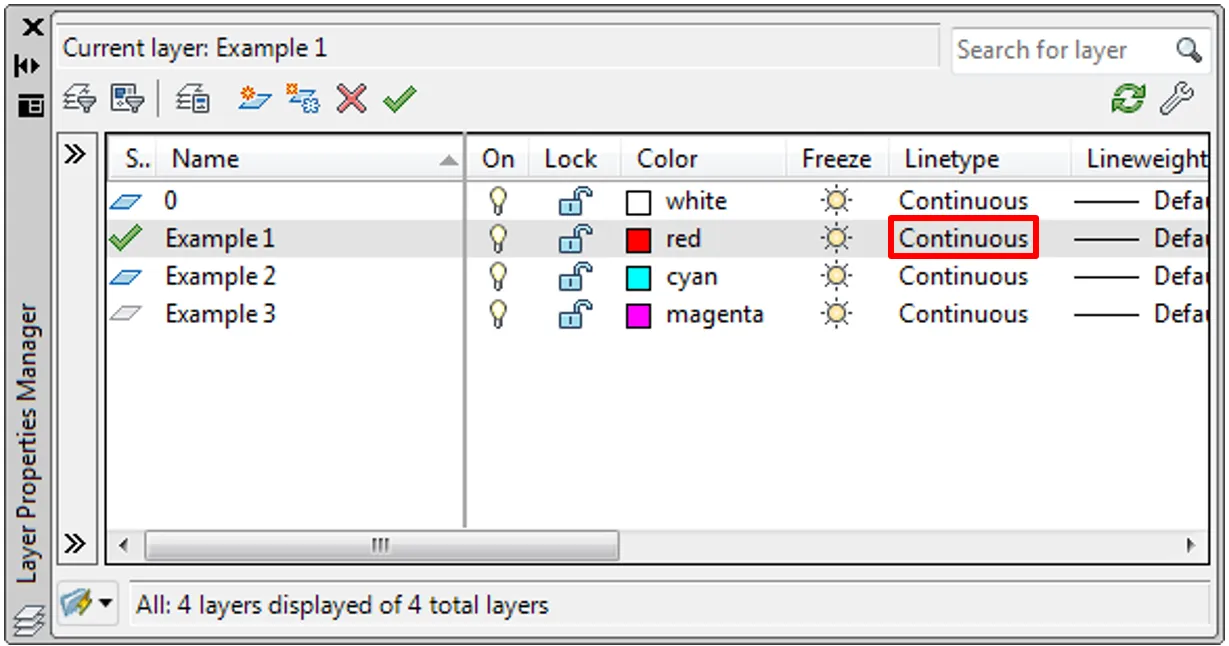
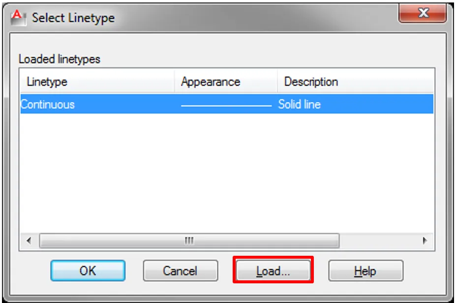
Within this manager, click on the linetype name of the layer you wish to modify. By default, this is set to “Continuous.” The Select Linetype dialog box will appear. Initially, only the continuous linetype is available. To expand your options, click Load… to browse the library.
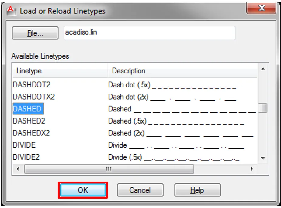
The Load or Reload Linetypes dialog presents a comprehensive list of available linetypes, such as HIDDEN, CENTER, DASHED, and PHANTOM. Select the desired linetype and confirm.
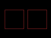
After loading, the new linetype will appear in the Select Linetype dialog. Choose it and click OK. The layer will now apply this linetype to all objects assigned to it, ensuring uniformity across the drawing.
 Layer Properties Manager with a layer now assigned to a new, non-continuous linetype
Overriding Linetypes for Individual Objects
There are scenarios where a specific element on a layer needs to stand out—perhaps a revision cloud on a layer that typically uses solid lines. To override a single object’s linetype, select the object. On the Ribbon’s Home tab, find the Properties panel. Click the Linetype drop-down menu to view all loaded linetypes and select the one you need.
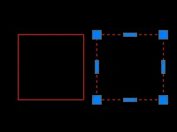 Drop-down list showing various linetype options available for a selected object
The result is a drawing where objects on the same layer maintain their layer properties except for the linetype, which is now a property-by-object exception.
Efficient Workflow with the Isolate Tool
When working on dense files with hundreds of layers and objects, focusing on a specific area can be challenging. While turning layers off is an option, it is often disruptive to the overall layer state. The Isolate tool offers a temporary solution that hides all objects except those you select, without altering layer settings.
To use this, select the objects you want to keep visible. Right-click to open the context menu, navigate to Isolate, and select Isolate Objects.
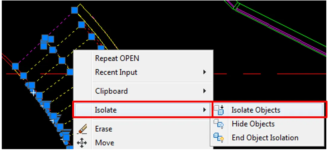 Context menu in AutoCAD showing the Isolate option with Isolate Objects highlighted
The drawing view will instantly refresh, displaying only the selected objects while temporarily hiding all others. This allows you to edit, snap to, or inspect these elements without visual clutter.
When the Isolate mode is active, a visual indicator appears on the Status Bar at the bottom of the AutoCAD window. The Isolate button will display a red bulb icon, signaling that the drawing is in isolation mode.
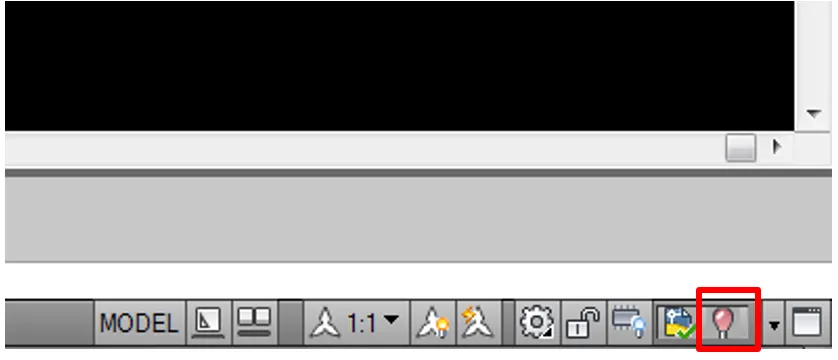 AutoCAD Status Bar showing Isolate button with red bulb icon indicating active isolation
To exit isolation, click the Isolate button again and select End Object Isolation.
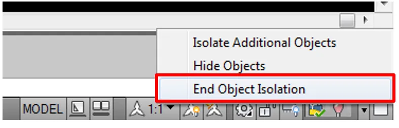 Isolate button drop-down menu with End Object Isolation option
Once isolation ends, the button returns to its default yellow bulb state. A crucial workflow note: isolation states are not saved with the drawing file. Closing the drawing automatically ends isolation, meaning you must rely on layer management for permanent view control.
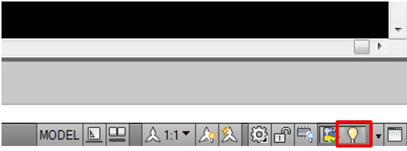 Isolate button showing yellow bulb, indicating no active isolation
Mastering Linetype Scale (LTSCALE and PSLTSCALE)
A linetype’s appearance is defined by a pattern of dashes, dots, and gaps. How that pattern appears on screen or paper depends entirely on scale. Mismanaged linetype scales are a common source of plot errors, where dashed lines appear solid or continuous lines appear broken.
Global Control with LTSCALE
The LTSCALE system variable controls the global linetype scale factor for the entire drawing. This setting acts as a multiplier for all non-continuous linetypes.
To modify it, type LTSCALE (or LTS) into the command line and press Enter. The prompt will ask for a new scale factor. The appropriate value is typically tied to the drawing’s output scale. For a drawing intended to be plotted at 1:100, a standard practice is to set LTSCALE to 100. This ensures the dash patterns appear as intended on the final print.
Viewport Control with PSLTSCALE
While LTSCALE manages the model space, PSLTSCALE (Paperspace Linetype Scale) controls how linetypes behave across different viewports in a layout. This variable is essential when working with multiple scales on a single sheet.
Type PSLTSCALE into the command line. The system variable accepts two primary values:
- 0: Linetypes are scaled based on the viewport’s scale. If you have one viewport at 1:50 and another at 1:200, the dash lengths will appear different in each, potentially causing visual inconsistency.
- 1 (Default): Linetypes use the global
LTSCALEvalue regardless of viewport scale. Dashes will display at the same physical length on paper across all viewports, ensuring uniform representation.
For professional plotting consistency, the default setting of 1 is preferred, as it guarantees that a dashed line looks identical whether it appears in a detailed blown-up section or an overall floor plan.
Fine-Tuning with Object Linetype Scale
Beyond global and viewport controls, individual objects can have their own linetype scale. This is useful when a specific element requires a denser or sparser dash pattern than the rest of the drawing.
Select an object, right-click, and choose Properties. In the Properties palette, find the Linetype scale field. Enter a value. Note that this value is a multiplier relative to the global LTSCALE. If LTSCALE is set to 100, setting an object’s individual scale to 2 results in an effective scale of 200 for that object.
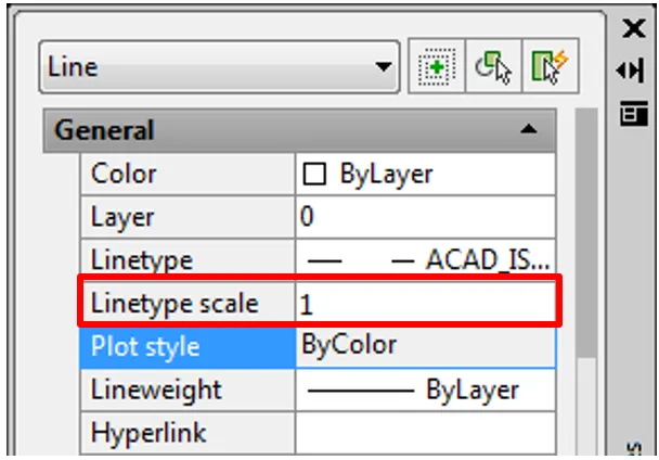 Properties palette with Linetype scale field highlighted for adjustment
Streamlining with Match Properties
Consistency is key in professional drafting. The Match Properties tool (command alias: MA) allows you to quickly apply the properties of a source object to multiple destination objects. This is significantly faster than manually adjusting each object’s layer, color, or linetype individually.
Activate the tool from the Home tab on the Ribbon, within the Clipboard panel, or by typing MA in the command line.
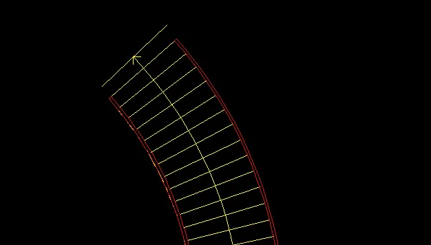
First, select the source object—the one with the properties you want to copy. This object’s properties, including layer, color, linetype, and linetype scale, become the template.
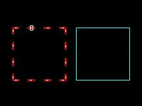 Cursor selecting the source object for Match Properties command
Next, select the destination objects. Each selected object will inherit the properties of the source. This command remains active until you press Enter, allowing you to reformat multiple objects rapidly.
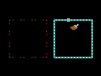 Selection of destination objects during Match Properties command
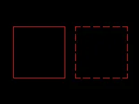
The result is a drawing where selected elements have been standardized to match the desired properties, ensuring visual and technical consistency.
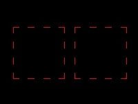 Final drawing showing objects now matching the properties of the source object
Conclusion
Efficient AutoCAD usage is built on a foundation of precise property management. By mastering the distinction between layer-based and object-based linetype controls, you maintain drawing standards without sacrificing flexibility. Integrating the Isolate tool into your workflow allows for distraction-free editing in complex files. Finally, a solid grasp of LTSCALE and PSLTSCALE ensures that the linetype patterns you design in model space translate accurately to printed sheets, regardless of viewport scales.
Applying these techniques consistently will not only reduce errors and plot corrections but also significantly accelerate your drafting speed. For further mastery, explore combining these tools with layer states and annotation scaling to build a fully optimized AutoCAD environment tailored to your specific industry needs.